The original power cap is one of those jumbo 4 in one caps which i am not interested in sourcing so i replaced it with several separate caps. The 30uf was replaced with 2 x 68uf in series (34 uf @ 800v), the 20uf's feeding A and B were replaced with pairs of 47uf's in series (23.5 uf @ 700v) and the last 20uf with a 22uf @ 450v. Overall this increases the total capacitance of the supply a bit resulting in a decreased power factor. Also to insure that the voltage is shared nicely between the capacitors in series i added dividers using 100k resistors. This will cause a bit more current to be drawn through the power transformer but since it is extremely large i don't think it will cause problems. (2.9mA on the B+, 2.85mA on 570 tap and 2.17 mA on the 433 tap = about 4 watts of power dissipated over the new voltage dividers). The 15k resistor was bumped up to 17k. Ideally the dividers should have been made with 220k and the 15k replaced with a 20k but its what i had on hand and it will work alright. With a 20k the voltages on the preamp taps would remain very close to the original design. with a 17k they are just a bit higher.
The caps on the negative bias voltage supply were also swapped out and replaced with the same type of 47uf mentioned above.
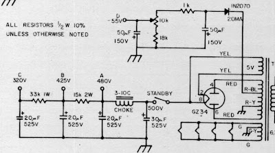
Here is the original supply schematic for reference:
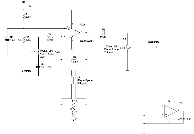
Below is a schematic of the new power supply capacitor section. The voltages are the end result measured after changing to solid state rectification. Unlabeled resistors are 100k 3 watt.

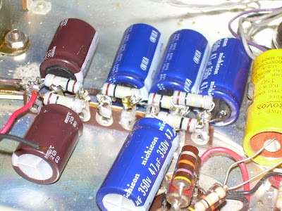
Here are some pictures of the physical layout, first the pairs of 68uf and 47uf.
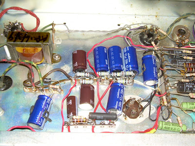
Here you can see all the electrolytics replaced.
The diode rectification is very simple to convert to. I have seen it suggested 10pf caps be put in parallel with each diode but i do not have any rated at the appropriate voltage so for now i have omitted them. Mostly you just have to make sure that the PIV rating of the diode is about 3 times greater than the rectified DC. In this case the resulting voltage is about 595 volts. And the PIV of a 1n4007 is 1000 volts. 3 X 595 = 1785. So if we use 2 diodes on each half of the rectifier we should be fine.
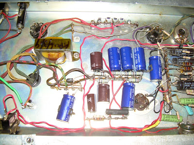
Here is a picture of the final result with the diode rectifier.
The amp was re biased for the new B+ and so far so good. It seems clearer sounding and punchier. It also seems to have a bit more gain. Possibly from the higher voltages in the preamp or possibly my imagination.