
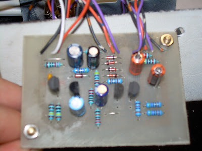
The PCB was made from the tonepad layout. However better bypass circuitry was added.
I perf boarded this pedal about 4 years ago and it worked but the output was so low. I asked about this on a forum and the situation was left unresolved.
the thread can be seen here.
Anyways years later here we are making another one and guess what? same deal. The output is about .6 volts. When you blend to the clean side its going to be at a volume level equal to whatever is coming in. Which in the case of any instrument I have is at least 2 volts and in terms of guitar more like 3 (courtesy of a dimarzio X2N). This works out to around a 12dB drop when the effect is switched on.
Quick searches of the tonepad comments and the DIYstompbox forum revealed that other people have noticed as well.
here and here
If you had low output pickups you might not notice. square waves sound louder than sine waves so the distorted sound will sound louder then a clean guitar signal with the same amplitude. (Rms of a sine wave is approx .707 * Amplitude, Rms of a perfect square wave = Amplitude) .
A lot of people are mentioning building a booster in the same box to bring the volume up. This is poor solution for a few reasons. This circuit calls for 3 high gain darlington transistors and has 2 gain stages and a buffer section. I shouldn't need to add anything to bring the level up.
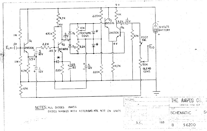
The problem can be resolved by modifying the final output stage comprised of Q3 and Q4. They are setup as a differential amplifier with a single ended output. Without doing to much math to calculate A (gain) = Rc / re'. Where Rc is the 1K resistor coming from +9v to the collector of Q4.
To calculate re' you must find the DC emitter current and so on. This is not necessary at this point as we can see from the equation in the last paragraph that Rc and A are directly proportional so increasing Rc will increase the gain. It will also however decrease the current through the transistor but this is of no consequence for our purposes.
I put mine up to 39k which gave me about 2.0 - 2.4 v out depending on the wave shape from a 3 v sine. (.707 * 3v = 2.12V so it should "sound" like about the same level). Since the clean part of the blend does not pass through this final differential gain stage its volume is unaffected. It would seem the problem is solved. I would suggest for anyone doing this to use a trim pot to find quickly they're preferred output level, 50k or 100k should be fine.


A millennium bypass was implemented after the board was made so thee are no traces for it.
Heres a video of the effect on a sine wave. The top trace is the output and the bottom is the input measured straight off the function generator. It gives a good idea of how the octave up is generated. First the effect is off. Its switched on when you see the square wave. Then the tone knob is twirled, then blend, then a bit of one and the other.
3 comments:
2 questions:
1. is it normal that the octave up sound is not audible in lower notes?
2. people say it only needs two diodes and other 3 on the schematic are not on the actual unit. is this true? what sound difference does that make?
i replaced the 1k with 39k and it's much loduer butit sounds like it decays quicker. why?
delayed response...
I remember taking out teh diodes with the asterix just to see and it did not seem to make a difference.
Also i have only built one but i did not notice the decay becoming faster once i changed the gain resistor.
Post a Comment